“Pedal-PI” clone with test code in C.
I wanted to investigate on how to grab Audio on a Raspbery PI Zero, using an MCP3002 (through ISP protocol) like pedal PI is doing.
I found this code on www.electrosmash.com, modified it to my needs.
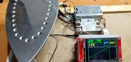
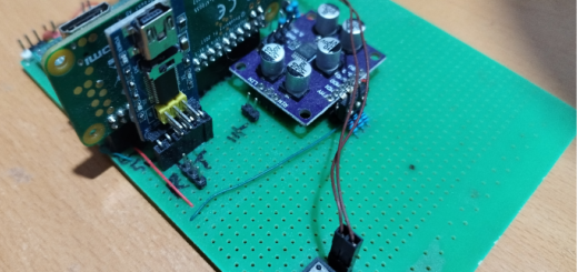
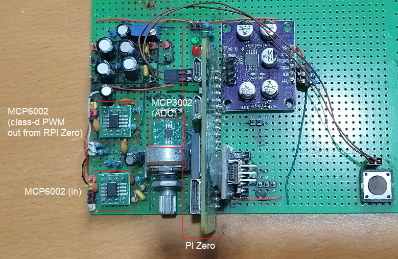
So I built a prototype on my home made development board.
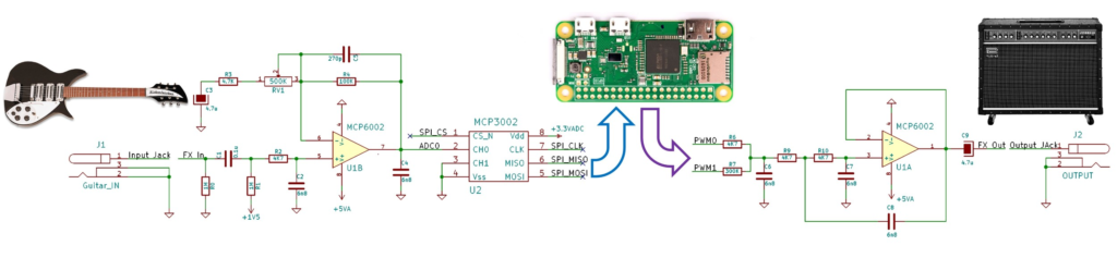
The main idea is to have the guitar signal input in a preamp chip (MCP6002) to buffer the sound, then sent to the ADC chip (MCP3002).
The raspberry PI then constantly reads the MCP3002 values through SPI protocol, modifies the sound or pass it as is.
The output buffer is then sent as PWM/Class-d type audio on two output pins of the RPI Zero.

Which is then used as dual inputs by the op-amp (MCP6002) which in turns creates an audio sound.
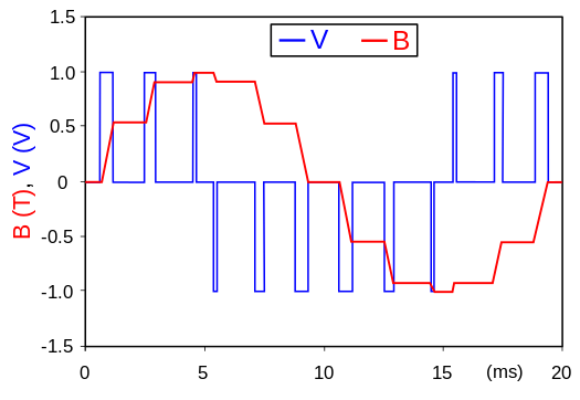
It is quiet amazing how the sound quality gets pretty much restored at the end.
The code is built and the binary file “adc” is launched from the shell.
gcc -o adc adc.c -lbcm2835 -lrt
sudo ./adc
I tried different effects and also a simple bypass.
Sadly, I found the RPI linux kernel even patched as RT linux, could not hold up decent performances without glitching the sound every seconds.
The code is here for documentation (not tested in a while, so provided as-is).
#include <bcm2835.h>
#include <stdio.h>

uint32_t read_timer=0;
uint32_t input_signal=0;

uint8_t effect_type=0;
uint32_t output_signal;

//variables for booster effect
uint32_t booster_value=4095; //good value to start.
//variables for fuzz effect
uint32_t distortion_value=2000;     //good value to start.
//variables for delay effect
#define DELAY_MAX 800000    //800000 is 4 seconds approx.
#define DELAY_MIN 0
uint32_t Delay_Buffer[DELAY_MAX];
uint32_t DelayCounter = 0;
uint32_t delay;

uint32_t DelayWrite = 0;
uint32_t DelayRead = 0;
uint32_t octaver_value = 1;
uint32_t Delay_Depth = 50000; //default starting delay is 100000 is 0.25 sec approx.

uint32_t read_timer, delay, divider;

//variables for echo effect
uint32_t Echo_Buffer[DELAY_MAX];

uint32_t bitcrushing_value=24; // 1 bit crushed by default.

int main(int argc, char **argv)
{
    // Start the BCM2835 Library to access GPIO.
    if (!bcm2835_init())
    {
      printf("bcm2835_init failed. Are you running as root??\n");
      return 1;
    }
	// Start the SPI BUS.
	if (!bcm2835_spi_begin())
    {
      printf("bcm2835_spi_begin failed. Are you running as root??\n");
      return 1;
    }

	//define PWM
    bcm2835_gpio_fsel(18,BCM2835_GPIO_FSEL_ALT5 ); //PWM0 signal on GPIO18
    bcm2835_gpio_fsel(13,BCM2835_GPIO_FSEL_ALT0 ); //PWM1 signal on GPIO13
    bcm2835_pwm_set_clock(2); 		// Max clk frequency (19.2MHz/2 = 9.6MHz)
    bcm2835_pwm_set_mode(0,1 , 1);  //channel 0, markspace mode, PWM enabled.
    bcm2835_pwm_set_range(0,64);    //channel 0, 64 is max range (6bits): 9.6MHz/64=150KHz switching PWM freq.
    bcm2835_pwm_set_mode(1, 1, 1);  //channel 1, markspace mode, PWM enabled.
    bcm2835_pwm_set_range(1,64);    //channel 0, 64 is max range (6bits): 9.6MHz/64=150KHz switching PWM freq.

	//define SPI bus configuration
    bcm2835_spi_setBitOrder(BCM2835_SPI_BIT_ORDER_MSBFIRST);      // The default
    bcm2835_spi_setDataMode(BCM2835_SPI_MODE0);                   // The default
    bcm2835_spi_setClockDivider(BCM2835_SPI_CLOCK_DIVIDER_64); 	  // 4MHz clock with _64
    bcm2835_spi_chipSelect(BCM2835_SPI_CS0);                      // The default
    bcm2835_spi_setChipSelectPolarity(BCM2835_SPI_CS0, LOW);      // the default

   	uint8_t mosi[10] = { 0x01, 0x00, 0x00 }; //12 bit ADC read 0x08 ch0, - 0c for ch1
	uint8_t miso[10] = { 0 };

    uint32_t sample=0;
    uint32_t divider=0;
    uint32_t max_count=1;
    //Define GPIO pins configuration
	uint32_t waveform[]= {0x800,0x80c,0x819,0x826,...}; // available on www.electrosmash.com/pedal-pi

	while(1) //Main Loop
	{
		//read 12 bits ADC
	    bcm2835_spi_transfernb(mosi, miso, 3);
	    input_signal = miso[2] + ((miso[1] & 0x0F) << 8);

        //**** EFFECT AREA***///
        // The effects are selected depending on effect type.
        switch(effect_type)
        {
            case 0://booster
            {
                /**** BOOSTER EFFECT ***/
                //The input_signal is attenuated depending on the value of booster_value
                //output_signal= input_signal;

                divider++;

                if (divider==max_count){ divider=0; sample++;}

                if(sample==999)sample=1;

                output_signal= waveform[sample]/*(int)(((float)input_signal) *  ((float)waveform[sample]/4095.0)*/;

            }
            break;

            case 1://booster
            {
                /**** BOOSTER EFFECT ***/
                //The input_signal is attenuated depending on the value of booster_value
                output_signal= (int)((float)(input_signal) * (float)((float) booster_value / (float) 4095.0));
            }
            break;

            case 2://fuzz distortion
                /**** FUZZ EFFECT ***/
            {
                output_signal= input_signal ;
                if (input_signal > 2047 + distortion_value) output_signal= 2047 + distortion_value;
                if (input_signal < 2047 - distortion_value) output_signal= 2047 - distortion_value;
            }
            break;

            case 3://delay
            {
                /**** DELAY EFFECT ***/
                Delay_Buffer[DelayCounter] = input_signal;
                DelayCounter++;
                if(DelayCounter >= Delay_Depth) DelayCounter = 0;
                {
                    output_signal = (Delay_Buffer[DelayCounter]+input_signal)>>1;
                }
            }
            break;

            case 4://echo
            {
                /**** ECHO EFFECT ***/
                Echo_Buffer[DelayCounter]  = (input_signal + Echo_Buffer[DelayCounter])>>1;
                DelayCounter++;
                if(DelayCounter >= Delay_Depth) DelayCounter = 0;
                {
                    output_signal = (input_signal + (Echo_Buffer[DelayCounter]))>>1;
                }
            }
            break;
            case 5://bit crusher
            {
                output_signal= input_signal<<bitcrushing_value;
                output_signal= output_signal>>bitcrushing_value;
            }
            break;
            case 6:
            {
                //save current reading
                Delay_Buffer[DelayWrite] = input_signal;

                //Increase/reset delay counter.
                DelayWrite++;
                if(DelayWrite >= Delay_Depth)
                {
                    DelayWrite = 0;
                }

                output_signal = Delay_Buffer[DelayRead];

                if (octaver_value == 2)
                {
                    DelayRead = DelayRead + 2;
                }
                if (octaver_value == 1)
                {
                    DelayRead = DelayRead + 1;
                }
                if (octaver_value == 0)
                {
                    divider++;
                    if (divider>=2)
                    {
                      DelayRead = DelayRead + 1;
                      divider=0;
                    }
                }

                if(DelayRead >= Delay_Depth)
                {
                    DelayRead = 0;
                }
            }
        }

		//generate output PWM signal 6 bits
	    bcm2835_pwm_set_data(1,output_signal & 0x3F);
	    bcm2835_pwm_set_data(0,output_signal >> 6);
    }

	//close all and exit
	bcm2835_spi_end();
    bcm2835_close();
    return 0;
}
Sources